
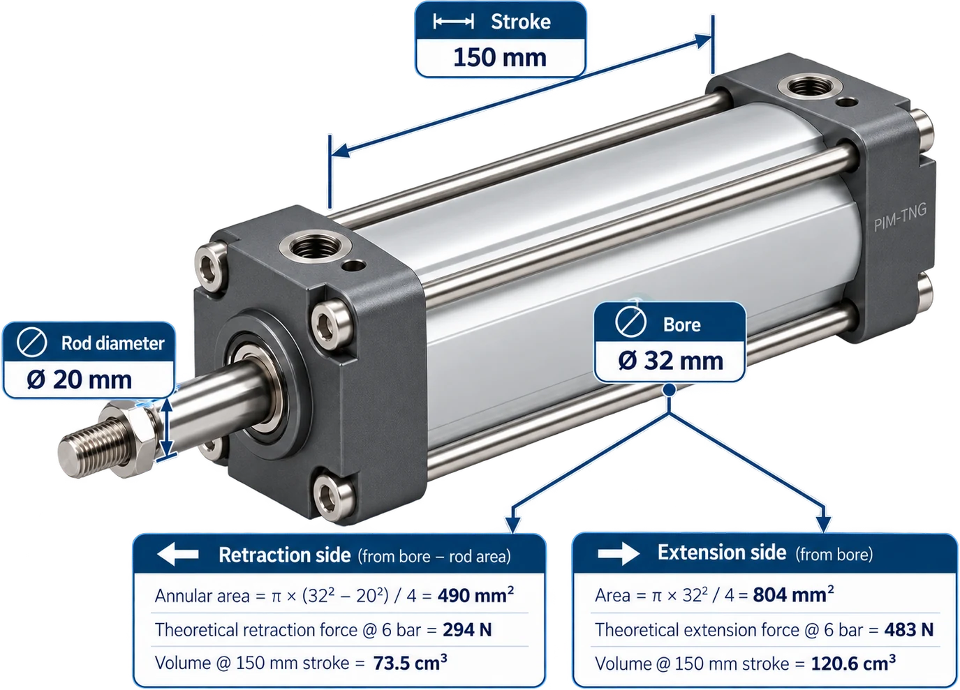
- Cylinder bore
- 63 mm
- Rod thread
- M16 × 1.5
- Port dimension
- G 3/8"
- Dimension A
- 25 mm
- Dimension B
- 32 mm
- Dimension K
- 74 mm
Industrial automation · Pneumatics
AXO ISO 15552 pneumatic cylinder
A cylinder is configured rather than picked off a list. One bore selection resolves a whole ISO dimension set, the stroke is a continuous variable that several other dimensions are calculated from, and the accessories, sensors and standards around it are relationships rather than variants.
Most fields are resolved or calculated.
01 Configured, not selected
This is not a fixed product with a part number you look up. Five decisions describe a cylinder, and two of them — the bore and the stroke — go on to determine most of the engineering data on the datasheet.
What describes one cylinder
- Operating type
- Double acting
- Rod configuration
- Standard, or double-sided rod
- Cylinder diameter
- Ø63 mm
- Cylinder stroke
- 500 mm
- Standard
- ISO 15552
The two marked decisions are the ones the next two sections are about: one resolves a table of fixed values, the other drives a calculation.
Why a cylinder is a bad fit for a flat catalog
A flat product table wants one row per sellable thing. A cylinder family has a stroke that is continuous within a range, so the honest row count is either enormous or a lie — and the usual resolution is a PDF of dimensional drawings that a human reads and a website that says “contact us”. Modeling the configuration instead means the sellable product is generated on demand and its dimensions are computed, so there is nothing to enumerate.
02 One selection changes more than one field
Choosing a bore does not set a field called diameter. It resolves an entire set of related engineering values, every one of which a distributor, a specifier or a CAD download will ask for separately.
In the model, 63 does not mean “diameter = 63”. It means this record — and the rest of the bore table behind it.
Whose numbers these are
The bore table comes from ISO 15552, not from the manufacturer: any compliant Ø63 cylinder has an M16 × 1.5 rod thread and a G 3/8" port, which is the entire point of the standard. That makes this section safe to publish and also makes the modeling argument sharper — the values are not a competitive secret, they are a table everybody in the industry already has, and the difference between manufacturers is whether their catalog actually resolves it or leaves it in a PDF.
03 The stroke is a variable, so the dimensions are calculated
A cylinder has one continuously variable dimension. As the stroke gets longer, parts of the cylinder get longer by exactly the same amount — so the manufacturer's drawing gives a formula rather than a table, and so does the catalog.
Configured stroke
500mm
Base dimension
Resolved
F
158
+ 500 =
658 mm
R
121
+ 500 =
621 mm
S
85.2
+ 500 =
585.2 mm
The base dimensions are fixed for the configuration; the stroke is the variable. Change the stroke and every dependent dimension follows, with no second set of values to maintain for every stroke length.
What F, R and S are — and what this replaces
They are references on the manufacturer's dimensional drawing, so their exact physical meaning is read off that drawing rather than invented here; the catalog's job is to resolve them, not to rename them. What it replaces is the alternative: a stored dimension set per stroke length. At 1 mm granularity over a 1,000 mm range that is a thousand rows per bore, per variant, all of which have to be regenerated when one base dimension is corrected. Here a correction is one number.
04 The configuration determines the product
The dimensions and the technical specification are consequences of the configuration. They are not a second body of data that somebody has to keep in step with it.
What follows from what
- Bore — the full ISO dimension set, resolved from one selection
- Stroke — every length dimension that moves with it, calculated
- Bore and rod configuration — which mounting kits and rod accessories fit
- Standard — which conformance claims the datasheet may carry
As the setup stores it
-
IF
Bore = 63 mmTHENRod thread = M16 × 1.5, Port = G 3/8" -
IF
Stroke = 500 mmTHENDimension F = 658 mm
The failure this removes
When resolved dimensions are stored rather than derived, they drift. A base dimension is corrected on the drawing, the drawing is reissued, and the catalog keeps serving the old overall length to every distributor feed and every CAD portal until somebody notices — usually the customer whose panel the cylinder no longer fits. Deriving them means the drawing and the catalog cannot disagree, because there is only one number.
05 The product code is an output
Same bargain as any generated code: it cannot disagree with the configuration it names, and an unfamiliar one off an order is a parse rather than a phone call.
AXO
Series
63
Bore
500
Stroke
DA
Action
M16
Rod thread
Codes that carry derived values
M16 is not a sixth decision — nobody chooses it, it falls out of Ø63. Putting it in the code is normal in this industry, because the code has to be readable by someone holding the part. It only works if the derivation is real: if the rod thread were a free text field, the code and the specification would be two independent claims about the same cylinder, and one of them would eventually be wrong.
06 The cylinder sits in a technical system
Accessories, sensors and standards relate to the configured product without being variants of it. A mounting kit is not a kind of cylinder, and a conformance claim is not an attribute someone types.
Product configuration
AXO Ø63 × 500
- is a variant of AXO Series
- conforms to ISO 15552 Standard
- is compatible with MKT-63-AO, RDA-16-B Mounting kit, rod accessory
- accepts PSS-24-NN Position sensor
- has documents Dimensional drawing, 3D model 2 assets
And where it is filed
Internal taxonomy
Industrial automation
Pneumatics
Pneumatic cylinders
ISO 15552 cylinders
Why compatibility is an edge, not a field
Written as text on the cylinder — “compatible with MKT-63-AO” — the statement is unusable: it cannot be searched from the kit's side, it cannot answer “what fits this cylinder” as a list, and it goes stale silently when the kit is superseded. As a relationship it answers in both directions, and a discontinued accessory reports exactly which configurations lose an option.
07 One model, different outputs
The engineer wants resolved dimensions, the distributor wants their own column headers, the website wants a sentence. All three are the same configuration, read differently.
Engineering
- Series: AXO
- Standard: ISO 15552
- Action: Double acting
- Bore: 63 mm
- Stroke: 500 mm
- Rod thread: M16 × 1.5
- Port: G 3/8"
- Overall F: 658 mm
- Overall R: 621 mm
Distributor export
- Manufacturer part number
- Series
- Standard
- Cylinder type
- Bore
- Stroke
- Rod thread
- Port size
- Overall dimensions
- Drawing
Website
AXO ISO 15552 Pneumatic Cylinder — double acting · Ø63 mm · 500 mm stroke
And a fourth that is a pipeline rather than a page: configuration → resolved engineering dimensions → product code → 2D drawing and 3D model.
How channels and exports workThe CAD output is the same resolution
A parametric 2D drawing and a 3D model need exactly what the engineering column above needs: the resolved bore table and the calculated length dimensions. They do not require a separate integration with its own copy of the geometry — they are one more consumer of the resolved configuration, which is why they cannot show a different cylinder from the datasheet beside them.
Bring us the product that breaks your spreadsheet
Not the easy one. The family with the option matrix, the rules nobody has written down and the ordering code somebody maintains by hand. That is the one worth modeling in front of you.